What are the Types Of Drawings Used in Piping?
As the pipings are going to carry explosive or non renewable energy sources, to draw piping system special attention needs to be provided. The process engineer prepares a schematic for process piping. To draw piping designs, five drawing types are used in sequence. These piping drawings will help communicate details about the construction and fabrication process easily.
General Arrangement(GA)
These drawings indicate where the main equipment is placed in the system. The top view of the piping system is represented most times.The GA diagram will show instrumentation,access ladders and platforms.

Process Flow Diagram
Process flow diagram is unscaled and denotes the materials to be conveyed by the piping system, the flow rate, number and types of pumps required and information about pressure or temperature. The process flow diagram does not include the pipe sizes or valve types.

P&ID Diagram (Piping and Instrumentation Diagram)
The P&ID is similar to the Process flow diagram but is more elaborate. It is a single line drawn schematic that will consist of major equipment, major valves, line sizes, controls and instruments.
Plot Plan Layout
A site plan is produced in this step with the help of which the process engineer will place and arrange equipment. The site plan is later modified and more elaborated into the plot plan which will display the coordinates, major items and dimensions of each plot

Orthographic and Isometric Drawings
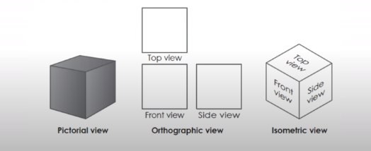
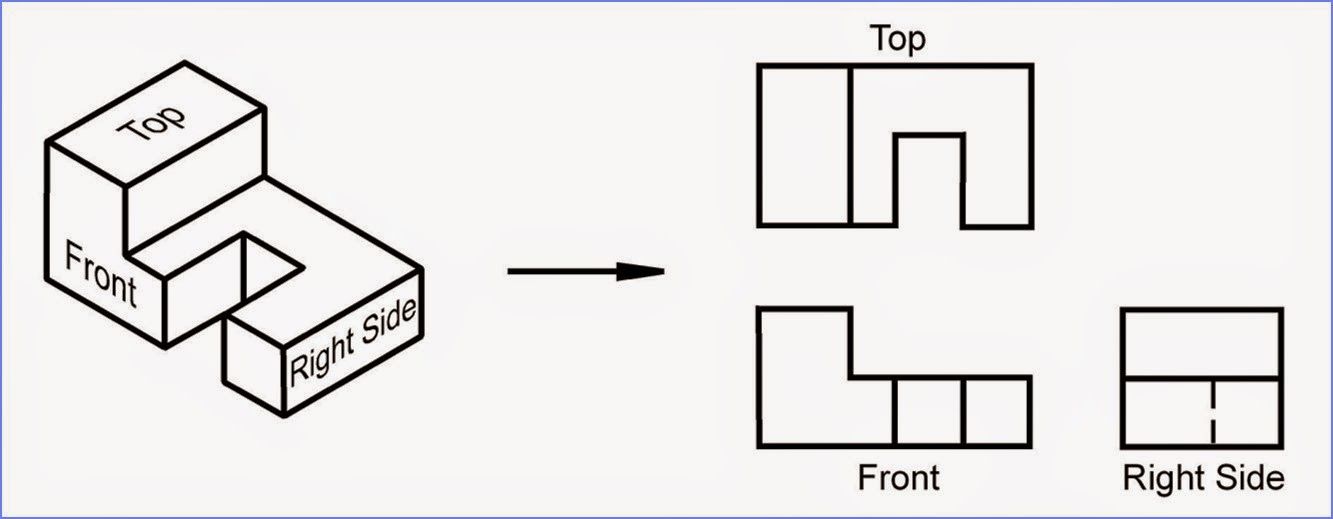
The drawing represents the process plan in different views as shown below. The orthographic view will represent a separate top, front and side view. The isometric on the other hand will represent all the three views in one drawing. If the piping system is in one single plane, orthographic view can be used. If the system is spread across various planes, an isometric view needs to be used.
Let us learn isometric drawing more in detail and how to draw isometric piping.
What are isometric drawings?
- An isometric drawing is a pictorial representation in which three sides of an object can be seen in one view.
- Isometric drawings are mostly used in the piping draw industry where a realistic view can be observed for laying out the pipes.
- It is mostly used as supplementary to plan ,GA, P&ID drawings
- The elevations and plan view drawings are used to prepare the isometric diagrams
- Isometrics provide a drafter that can calculate angular offset in pipe run.
- Isometric diagrams are not drawn on any scale. Dimensions need to be specified in such a case to denote the size and length of the pipe that is running in the process system.
Advantages of using isometric drawings
- Simple to draw – As compared to orthographic views, iso views are simple to draw and can be read easily and understood better. The piping draw will provide easy understanding of the different planes through which the pipes move
- Lesser number of drawings needed- Isometric view needs lesser drawings than orthographic view. For eg. If you notice the image attached below, the orthographic view needs the top, front and side view. On the other hand the isometric drawing can be one single work.
- Can be used to represent a pipe in different planes – If a pipe is running north, south, east and west; the orthographic view cannot represent all these directions in a single drawing. On the other hand isometric drawing can easily represent various directions in a single drawing
- The isometric also denote which piping lines need to be assembled and joined in the welding shop and which ones can be assembled directly on the field
How are various piping elements drawn in an isometric view?
Fittings
Fittings in piping draw systems help to regulate flow and to join straight sections of a pipe to different shapes, sizes. In isometric drawing these fittings are represented as follows

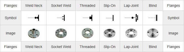
Flanges
Flanges are used to connect various components like pipes, valves or pumps to form a piping system
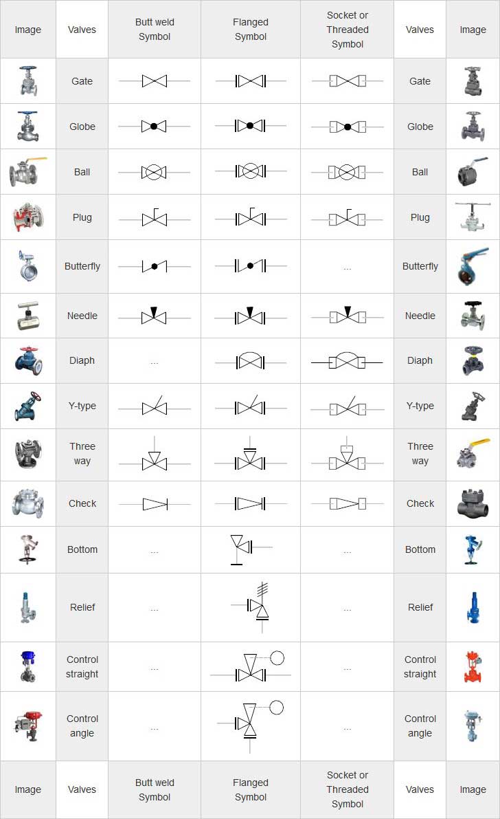
Valves
Valves are equipment that are used in the piping draw systems to control the pressure and flow.
Miscellaneous
All the other piping draw equipments and instruments fall into this category

What are the different parts of an isometric drawing?
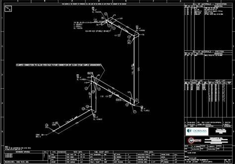
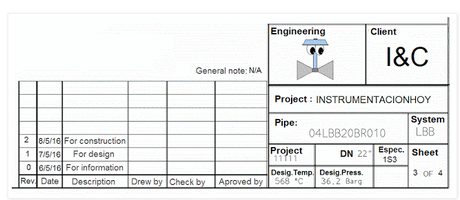
Title Block
Every isometric drawing should have a block that includes the following details
- Pipe code. Each pipe must be coded in the isometric drawing For eg: 04LBB20BR0100
- Page number: For eg. 3 of 5
- Pipe design conditions. For eg: 430ºC
- Pipe Specifications For eg: E340
- Diameter of pipe . For eg 15″
- Any changes made in the Revision section.
- Document in charge and all people involved (Client, engineer,approver etc…)
- Project system and Name of the Project
Pipe Design/Drawing
This is the most important part of the isometric piping draw process. The dimensions, coordinates,insulation areas, location of supports,orientation angles, etc are present in the drawings
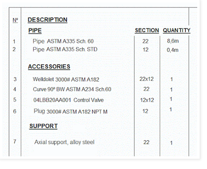
Bill of Material List
The material list includes description, quantity, thickness, dimensions, etc of the material that needs to be used.
How to draw isometric piping drawing?
Isometric piping draw represent the centerline of the pipe.The dimensions are measured from the centerline of the pipe. The outer fittings are not considered for measuring. Here are a few things to keep in mind about how to draw isometric piping and how to read isometric piping.
Piping offset
Offset is present in the design when a pipe with move in an angle other than 90 degree. In case a 45 degree elbow or an old nozzle is used in such cases the piping offset is used. The simple trigonometry and pythagoras theorem is used to determine the pipe length with the offset.
North Arrow
The north arrow is drawn to denote the direction in which the pipes in the piping system run. It also helps understand the elevations and depression directions properly
Connections
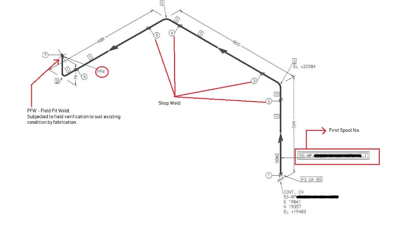
Connections made using welding, soldering or gluing have to be shown on the isometric drawing. All connections have to be denoted by a bold dot in the piping draw. There is a note that will explain the type of connections to be used in that place.A single thick line denotes connections that are detachable. The flanges or coupling connections will be defined in the Bill of Material section.

How to draw Isometric Piping Drawings by hand?
Isometric drawings can be done by both. Let us explore the basics about how to draw isometric piping drawings by hand. Make sure you note the above mentioned points before going ahead to draw isometric drawings by hand.
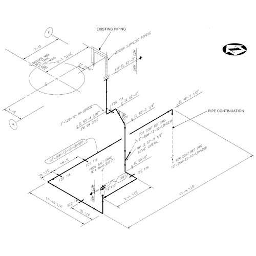
In the figure below you will see both the isometric and orthographic view. Let us see how the isometric piping draw is read differently from the orthographic drawing. The image is an orthographic drawing of the butt welded pipe. The pipe has three sizes A,B and C. The dimension A and C is from the front till the centerline of the elbow.B is measured from the centerline of one part and the centerline of the other part.
Now if you notice the isometric drawing you will see that the isometric view is similar to the orthographic view where the red lines are for the pipes. The bold black dots denote the butt welds. Isometric drawings are drawn in an auxillary cube as compared to orthographic drawings There is an offset marked with the North direction as reference.
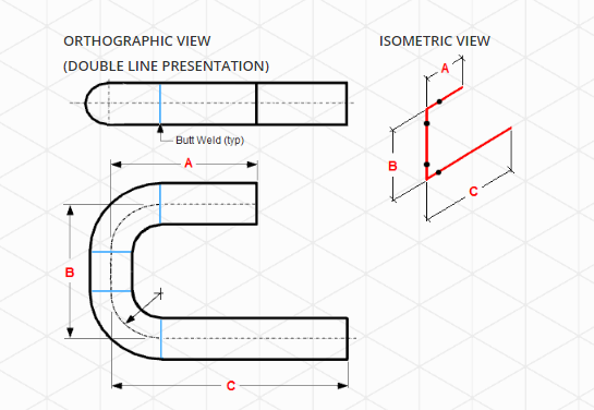
In the below figure the pipe runs first to the east, then goes up. The pipe then runs towards north. It moves towards the west and finally runs down.

Hatches are used in isometric drawings to show a certain angle in which the pipe is placed and the direction in which the pipe runs. In the above figure the piping starts at point X and runs up. The pipe then runs to the east and finally runs up.

What do you need to check before implementing the Isometric Drawings?
The isometric drawing is the last step of the piping design. In the previous four steps, the drawing will undergo innumerable changes and updating. The material type, dimensions, elevation angles,etc can be changed as per design updates and in newer versions. There can be many minor and major changes too. Make sure you are working on the right version type. After the isometric drawing is complete, check it with the P&ID system drawings to verify the materials used. Here is a list of a few things you need to verify before implementing the isometric drawing.
- Revision – Make sure you are working on the latest revised version that has been approved by the client and your team leads
- Line Number – Check the line number before you start implementing the system. The line number can be checked in the P&ID drawings to verify the size, material and insulation etc
- P&ID No – Compare the information given in the ISO diagrams and the P&ID. Do not go ahead if the details are not matching up
- Notes- Make note of all the notes and instructions to be followed. Remove any irrelevant notes that are not required anymore.
- North Arrow – Make sure there is a north arrow and it is aligned with the GA and Plan layout drawings
- Design and Operating point – Make special note of the temperature and other operating conditions based on the Stress Category. Make sure the ISO is according to the Stress Analysis report
- Flow direction – The flow direction in ISO and P&ID should match
- Bill of Material – Make sure the quantity, numbering and specifications are all sufficient as per requirement.
- Insulations- The insulations, their length, type and all details as mentioned in P&ID should be present in ISO.
Choosing the Right Software for Piping Design
Choosing the right software is very essential for a process engineer. The right software will help automate a few tasks and avoid erroneous submissions in the drawing. However, before choosing the right software you should have an idea on how to draw isometric piping
Factors to Consider while Choosing a Piping Design Software
- Compare the price and value- While purchasing the software, make sure you cross check the features and specifications. Do not be of the opinion that a costly software will be better. You can also achieve all your required features from a cheaper software. Do not invest in a software whose advanced features you may never use
- Adaptability- Softwares assist employees and reduce the work burden and flaws.Your employees and team members should be able to easily adapt to the software. An advanced complex model will only lead to more confusion with the employees. Consider taking up recommendations from team members before purchasing the software.
- Support- Every software you purchase should provide you training material and technical support. Make sure you purchase a software that provides call support and not just a ticket raising system. The ticket raising system will not necessarily provide timely immediate attention to your queries and complaints.
- Compatibility- Before purchasing the software, test if it is compatible with your current OS. Also, the software should have the flexibility to export and import designs from other systems you use.
Autocad for Piping Design
AutoCAD is considered as one of the most efficient systems for isometric piping designs. The Autocad Software comes with a user manual that will help you answer queries regarding how to draw piping isometrics in autocad Use the SNAP mode to enter the software into isometric mode. After typing DS on the command line and pressing enter. In the drafting setting window, choose the snap and grid tab.
Click on the isometric view in this tab.Click F5 to choose isometric plane. Autocad also has many discussion forums and technical support staff that will guide you on how to draw piping isometrics in autocad
A piping system is used to transport fluid from one place to another. With the revolution in nuclear and atomic energy research, the kind of fluids to be transported include water, harmful gases, natural gas, fuel and other fluids in liquid and gaseous states.Make sure you choose a software based on your requirements.
Check all the specifications and features offered by the software before purchasing them. You can also make use of a trial version of the software to test the performance. Ease of operation, customization,cost, flexibility, inter application operations are some of the desired features that a piping software should provide.